
NTP is a protocol which allows a customer to be synchronized starting from a TCP/IP network.It was developed to provide a UTC (Universal Time Co-ordinated) of a precision about the millisecond for LAN network and about 50 milliseconds for WAN.
1) INTRODUCTION
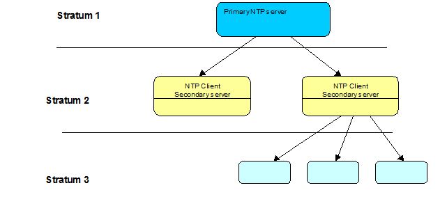
NTP Protocol is built on following architecture:
- At the highest level, one finds a NTP server called Stratum 1 server (or primary server), its role is to provide a UTC time. This server is synchronized on a reference clock: atomic clock, GPS,…
- UTC Time is then available for a client which can synchronize its internal clock. Once synchronized, this calculator is able to provide its time to another group of calculator. This calculator is named “server Stratum 2″.
- We will call server Stratum N, any calculator which is synchronized on a server stratum N-1. Consequently, the smaller the stratum number, the higher the accuracy.
2) OPERATING MODE
The following figure shows the client/server mechanism:
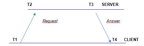
- T1 or “Originate TimeStamp” time at the time when the request is sent according to the client clock
- T2 or “Receive TimeStamp”, time at the time when the server received the request according to its clock
- T3 or “Transmitted TimeStamp” time to the moment when the answer is returned according to the server clock
- T4 or “TimeStamp Reference” time to the moment when the answer is received by the client according to his clock.
The delay or time to go and return is given by the formula:
delays = (T4-T1) – (T3-T2)
The offset is obtained by:
Offset = ½ * ((T2- (T1+Délais/2)) + ((T3+Délais/2) – T4))
Offset = ½ * ((T2-T1) + (T3-T4))
To make an right estimate of the time to go and return and the offset between the two clocks, the protocol NTP must record four information of time in its NTP frame.
3)FORMAT OF NTP MESSAGE
Protocol NTP is built on UDP/IP, which implies:
- No concept of opening and closing connection
- In the event of loss of packet, there is no re-emitting mechanism
After the UDP header, the NTP message is found:
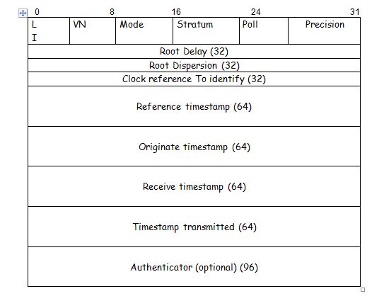
The significance of the various fields is as follows:
- LI or Leap Indicator: it is a field of two bits for the indication of the jumps of seconds in time NTP. The codes are:
- No alarm
- The duration of the last minute of the day will be 61 seconds
- The duration of the last minute of the day will be 59 seconds
- Indicator of alarm (not synchronized clock)
- VN or Number Version: this field of three bits, gives the version of NTP message.
- Mode: this field of three bits gives us the mode of the transmitter. The various codes are:
- 0: reserved
- 1: active symmetric
- 2: passive symmetric
- 3: customer
- 4: server
- 5: broadcast
- 6: reserved for the monitoring of NTP message (additional information on mode 6 are given in the appendix B of the RFC 1305)
- 7: reserved for personal use
- Stratum: this field of 8 bits indicates the level of the transmitting server.
- 0: no indication
- 1: Primary server (atomic clock, GPS…)
- 2 – 255: secondary server (via NTP)
- Interval poll: this field of eight signed bits indicates the maximum number of second which can run out between two messages (expressed in power of two).
- Precision: this field of eight signed bits indicates the precision of the clock in second (expressed in power of 2, -10 means 2-10, that is to say 1/1024=0.97ms)
- Root Delay: this signed value of 32 bits, indicates in fixed point, total time to go and return, in second, between the customer and the primary server. The comma is between bit 15 and bit 16. The value of this field can be positive or negative according to the precision of the clock of the server.
- Root Dispersion: this signed of 32 bits, indicates in fixed point, the estimated dispersion of the primary server. The comma is between bit 15 and bit 16. Only the values higher than zero are authorized.
- Clock reference identifier: for the primary servers, this field of 32 bits indicates the type of reference clock. This indication is carried out with a character string, justified on the left with one zero terminal. This chain can take the following values:
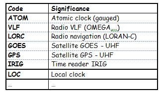
Note: When the number of stratum is higher than 1, this field contains address IP of the reference server.
- Reference TimeStamp, Originate TimeStamp, Receive TimeStamp, Transmit TimeStamp: those fields of 64 bits contain the four informations of time in connection with the “delays” and “the offset”. The first 32 bits indicate the number of seconds passed since January 1, 1900 to 0h00 UTC. The last 32 bits indicate the 1/232 seconds number spent since the beginning of the current second. In Broadcast mode, the fields Originate TimeStamp and Receive TimeStamp are by convention set to zero.
- TimeStamp reference: time of the last update of the clock
- Originate TimeStamp: time of departure of the request.
- Receive TimeStamp: time of arrival of the request
- TimeStamp transmitted: time of departure of the response to the request.
- Authenticator (optional): this fields is kept for the mechanism of authentication of NTP messages. This mechanism authorizes the encoding of NTP data with the DES (Data Encryption Standard). It is packed up in the appendix C of the RFC 1305.